Title

While the main focus of the Strathspey Railway is running steam trains for the paying public, a small but dedicated group of volunteers has been restoring other items of heritage interest in spare moments between working on the loco fleet and improving locoshed infrastructure and facilities.

The current project is a Ruston Hornsby 48DS diesel shunter of 1948 which worked at Longmorn distillery until 1980 (even though Dr Beeching had closed the adjacent main line in 1967). Because it was presented to the Strathspey Railway repainted with advertisements for Queen Anne blended scotch whisky, it is known to most people as “Queen Anne”.

To find out more about our aims, follow this link or click the [About] button above.

This Blog was started over 5 years after the project began, so most of the initial blog entries are retrospective.

Sunday 3 December 2023

Gearbox Refurbishment - Part 3

More Pictures

Here are some more photographs of the internals of the gearbox.

Clutch drum and various bits

Detail of the clutch operating levers

Fast Gear

The fast gear clutch connects the input and output gears (1 to 1 ratio).  The friction plate is gripped between a fixed plate that is part of the clutch drum and a moving plate connected to one set of operating levers. 

The friction disc with its linings

Clamping plates either side

The fast gear friction plate
 

The brown discolouration of the fast gear friction plate is probably due to oil staining and not due to overheating.

Slow Gear

The slow gear clutch shows signs of overheating on various parts.  The spindles that operate the clamping plates are also discoloured at a place where they are adjacent to the slow gear clutch.  The blue colouring indicates that at some time the steel has been heated to around 290 degrees centigrade.


Slow gear clamping ring

Slow gear friction plate and spindles

The other side of the slow gear friction plate

New Friction Linings

 Investigations are ongoing regarding replacement of the friction linings.  There is a company in Cumbernauld that undertakes this type of work.  In fact they have relined a Ruston 48DS gearbox for a group at Prestongrange Mining Museum.

Another group restoring a 48DS at the Chasewater Railway has also given some useful advice.

It has not been decided yet if riveting or bonding of the friction plates is the best solution.


Tuesday 7 November 2023

Gearbox Refurbishment - Part 2

Gear Assembly Removal

 To remove the gear assembly it was first lifted manually using rope and steel bars sufficienty to enable two poles to be inserted underneath and raise it slightly above the casing.

After that, Queen Anne was towed outside to allow removal via the cab entrance using a forklift.  Strops were used to attach the assembly as closely as possible to the tine of the forklift.  The lower part of the cab entrance is too narrow for the gear assembly to pass through, but it will fit through the upper part.  However it needs to be lifted to the full height of the cab.

Forklift in position

Strops attached

Have we got enough clearance?

Out it comes - no problem


The assembly was then lowered onto a sturdy trolley and wheeled to the Clean Room for dismantling.


Dismantling started

Disassembly

A gear puller was required to remove the ball bearing and roller bearing that form the rear bearing assembly.  Following that the gears can be slid off and the rear face of the clutch drum unbolted.

The next part to be removed is the clutch friction plate for Slow Gear.  On removing the rear face of the clutch drum the friction material was found to have completely disintegrated.  The clutch disc should have a ring of friction material on both sides, held in place by brass rivets.  In fact both friction rings had deganerated into a fibrous mass.  It is amazing that Slow Gear could be made to supply any drive at all.

It seems likely that the locomotive must have been run for some time in Slow Gear with the clutch slipping, causing overheating and breakdown of the friction material.

Friction plate showing the rivets which once held the friction material


The remains of the friction material


Clutch rubbing plate

To engage slow gear the friction plate is squeezed between the moveable rubbing plate (pictured above) and the rear cover of the drum assembly.

A useful description of the operation of this type of gearbox can be found HERE.  It contains colour-coded diagrams showing how power is transmitted in each gear.  The website is run by the Moseley Railway Trust.

Sunday 29 October 2023

Gearbox Refurbishment - Part 1

Clutch Problems

The Ruston gearbox fitted to Queen Anne has three gears - slow, medium and fast.  The different gears are in constant mesh, but each ratio has its own friction plate clutch.  Gear selection is achieved by engaging the appropriate clutch via the gear change lever.
 
We have known for some time that slow gear is not very effective - its clutch slips.  There is an adjustment for the spring that applies pressure when the clutch is engaged but while this can make the clutch more effective the resulting pressure is obviously excessive.  The friction plates are riveted to steel disks and it is very likely that the friction material for slow gear has worn down to the rivets.

The replacement of the friction linings is part of normal maintenance for this type of gearbox and is described in the locomotive manual.  Other restoration groups have carried out this work and there are companies who specialize in relining friction plate clutches for heritage vehicles.

The whole gear assembly can be lifted out once the gearbox cover is removed and the assembly stripped down on the bench.

Gearbox Cover Removal

Queen Anne has been kept in the carriage storage shed recently so the first step was to get her moved into the locoshed.
 
Queen Anne being manoeuvred into place

On Road 4 ready to start work
 
The first step is to remove the central floor sections - no problem as they are now secured using stainless steel screws/bolts.  Then the gear change unit must be unbolted from the side of the gearbox.


Central floor removed

Once all the nuts and bolts for the gearbox cover have been removed lifting eyes are screwed into the two positions on the top of the cover.  Because the cover weighs 3 cwt it was decided to use two steel bars and four jacks to lift the cover off.  Since the cover needs to be lifted to at least cab floor level, this required "jacking and packing" using wood blocks.

Jacking system in place

Packed up with wood blocks

Poles inserted underneath the cover

Once the cover had been lifted high enough, poles were rolled underneath and the cover lowered onto them.  The cover could then be slid sideways to sit on the floor at the left-hand side of the cab.

The gearbox mechanism

The above picture shows the gearbox assembly.  From left to right, the main components are :-
  • The output gear to the forward/reverse box.
  • Bearing.
  • The input gear from the drive shaft in the gearbox casing.
  • Fast gear clutch operating ring. 
  • Medium/Slow gear clutch operating ring.
  • Drum containing the clutch plates.
  • Gears providing the different ratios.  The lay gear for this can be seen underneath.
  • Bearing.
As can be seen, the whole assembly simply lifts out.  Further updates will be published as work progresses.
 

Monday 24 April 2023

Chain Oiler and Diesel Gala

The Chain Oilers

The chain oilers have finally been completed.  A drip-type oil pot is attached to a solenoid valve which is energised while the engine is running.  A pipe feeds the oil to a special brush which is mounted on an adjustable arm to spread the oil over the chain.  There are two separate oilers, one for each chain.

The brushes need to be mounted close to the sprocket on the reversing gearbox.  In any other position they would be vulnerable to the chain whipping or movement of the suspension.  There is not much room near the sprockets so mounting them is tricky.

The following photographs show the setup.
 
An oil pot with its solenoid valve

The LH brush. A very cramped location.

RH brush showing the adjustable mounting arm

Excess Fuel Device

In order for the engine to start (especially when the engine is cold), it is usually necessary to squirt more fuel than normal through the injectors to get it running.  To do this a device is fitted to the control rod that regulates the fuel injection pump.  This device is a brass casting with lugs that is lifted up to allow the control rod to move forward and inject more fuel.  Once the engine is up to speed, the governor pulls the control rod back and the device drops down to its working position, limiting the maximum amount of fuel delivered.
 
Often the engine will start to fire and pick up speed causing the device to drop back, but the engine still needs to warm up a bit more and so the engine stalls.  If the device is lifted up again the engine will pick up speed and eventually run on its own.  Except in very warm weather it needs to be lifted two or three times before the engine will run on its own.

The problem with the original arrangement is that the device is not visible unless you peer inside the engine compartment, so you have to feel for it.  The device is close to the fan belt and other moving parts, so you need to know exactly where the device is.  For this reason it was decided to make an accessible lever to operate the device.  A bracket bolted to the engine block was modified to take the new lever and a flexible steel wire was used to pull up the lug on the excess fuel device.

So to start, all you have to do now is to open the right-hand bonnel door and pull down the lever before starting, and possibly pull it down once or twice more until the engine runs freely on its own.

The new excess fuel lever on the front of the engine

The brass casting and its lug is shown in the circle

Diesel (mixed traffic) Gala 2023


This year's Diesel Gala (7th to 10th April 2023) had Queen Anne offering footplate rides in Aviemore yard.  Things were a lot quieter than the 2022 Gala but those that came on board seemed to enjoy the experience.

Queen Anne also did a couple of "taxi rides" to Aviemore station - a first for the loco.  Here are some photos of the event :-

Queen Anne and the Class 31

Class 37 approaching

In the loop at Aviemore Station

And a video on Youtube :-

Queen Anne also features in some other Youtube videos of the Gala.  See the "Queen Anne Videos" page above for links to these.


Monday 21 November 2022

Earliest Distillery Shunters and other news

The Earliest Distillery Shunters

While many distilleries had sidings connected to the main line, few had their own shunters.  One source quotes the Ardgowan distillery on the south bank of the Clyde near Greenock as having its own Barclay 0-4-0ST built in 1894.  Several Speyside distilleries bought their own shunting locomotives in the late 1890s – Glenlossie (part of the private rail network at Longmorn) in 1896, Daluaine 1897 and Balmenach 1897.  Longmorn Distillery’s first locomotive was a McLaren 2-2-0 “traction engine” locomotive of 1898.

The reason for mentioning these early locomotives is that we are now in possession of two lamps that were originally fitted to Longmorn’s McLaren 2-2-0 of 1898.  A man (name unknown) who had previous associations with Longmorn distillery came to the 
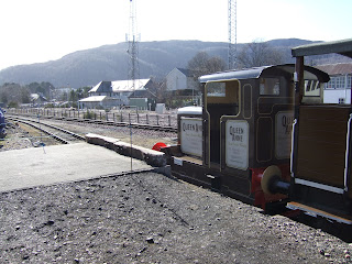
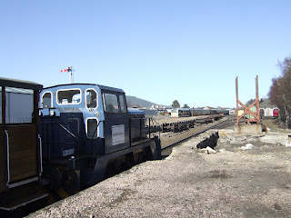
locoshed to donate the lamps in his possession.  It is believed that he was given a footplate ride on Queen Anne at the 2022 Strathspey Diesel Gala – thank you very much for your generous donation.  The McLaren was in use until 1948 when Queen Anne was bought to replace it.

The lamps are of a style fitted to traction engines as they have one forward facing lens and a second window on one side.  They are a right and left-handed pair that were carried on either side of the smokebox.  There is a photograph on the Railscot website that shows the discarded McLaren locomotive at Longmorn around 1951 and you can see a lamp bracket on the side of the smokebox.

Note lamp bracket on the smokebox
 

Click here to view the full image on the Railscot website.

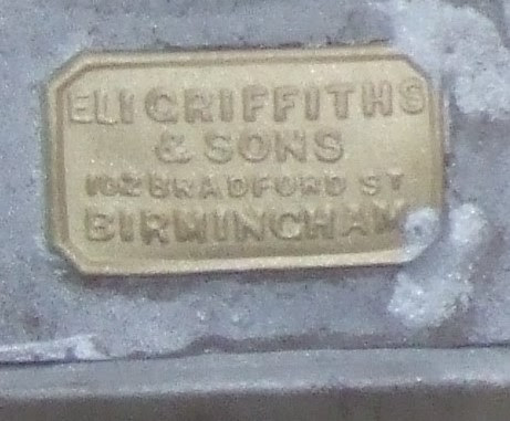
The lamps are made of tinplate by Eli Griffiths of Birmingham.  They had been painted latterly in bronze metallic paint and were in moderate condition.  After blasting away the paint, one lamp was in very good condition with only minor corrosion, although the tin plating had largely gone.  The other had more corrosion and will need repairs with tinplate.  The removable paraffin burners inside were also in need of repair.  Their butt-soldered joints had obviously caused problems with leakage in the past and the wick holders were missing.

The lamps as donated

Maker's plate on oil burner

It was decided to restore the lamps retaining as much as possible of the original material and dents etc.  After cleaning, the better lamp was painted with 2-part epoxy primer to prevent further corrosion and then sprayed gloss black.  The other lamp will need repairs before getting similar treatment.  The burners were repaired with tinplate.  Strips of folded tinplate were soldered over the edges where paraffin leakage had been a problem.  A spare wick holder from a different lamp was found and adapted to fit one of the lamps.  A second identical brass filler/vent was turned up to replace one that was missing.

Restored Lamp

Restored oil burners
 

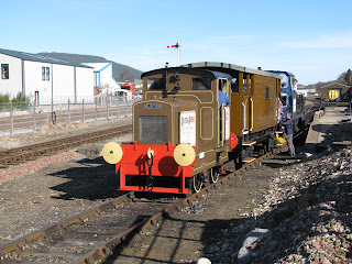
The Strathspey Railway doesn’t really have any safe storage for historic items so the lamps will remain with Queen Anne for now.  One possibility is to bolt on temporary lamp brackets on either side of the locomotive at the front.  Queen Anne is already the guardian of one historic item – a Highland Green watering can with the legend “HR REDCASTLE” painted on the side.  Redcastle was a station on the old Black Isle line to Fortrose.  A long time ago this item had been in the collection of a small museum at Boat of Garten, but it was found in the skip.  After repairing the spout, it is now used to top up Queen Anne’s radiator.

Chain Oilers

The oiling system is still not complete.  The brush oilers have been obtained and these need to be fitted in place and connected to the oil pots.  Brackets have been made and piping obtained.

The oil pots and their solenoid valves have been fitted and wired in so that they dispanse oil when the engine is running.

One of the oil pots with solenoid valve

Control Box Improvement

The four electrical push/pull switches on the control box were fixed in with mild steel fittings.  However these had become corroded in the damp atmosphere of the locoshed.  It was decided to make new fittings out of stainless steel and these have now replaced the old mild steel ones.

The old mild steel fittings

Control box with stainless fittings

Gearbox Oil Valve

The Ruston 48DS gearbox has a slightly odd lubrication system.  There is a valve that is accessible through a hole in the cab floor and operated by a special key.  The valve should be closed while running but turned to the open position when the locomotive is not in use.  A sign in the form of a brass disc was created using the CNC router at Kingussie High School to do the engraving.  The sign reminds the driver to turn the valve clockwise (close) while running and anticlockwise (open) when stopped.  Three Terry Clips were screwed to the bulkhead in the cab to hold the special key to operate the valve.

The engraved sign

Special operating key
 

Hopefully this will remind drivers of the correct procedure to follow.

Memorabilia

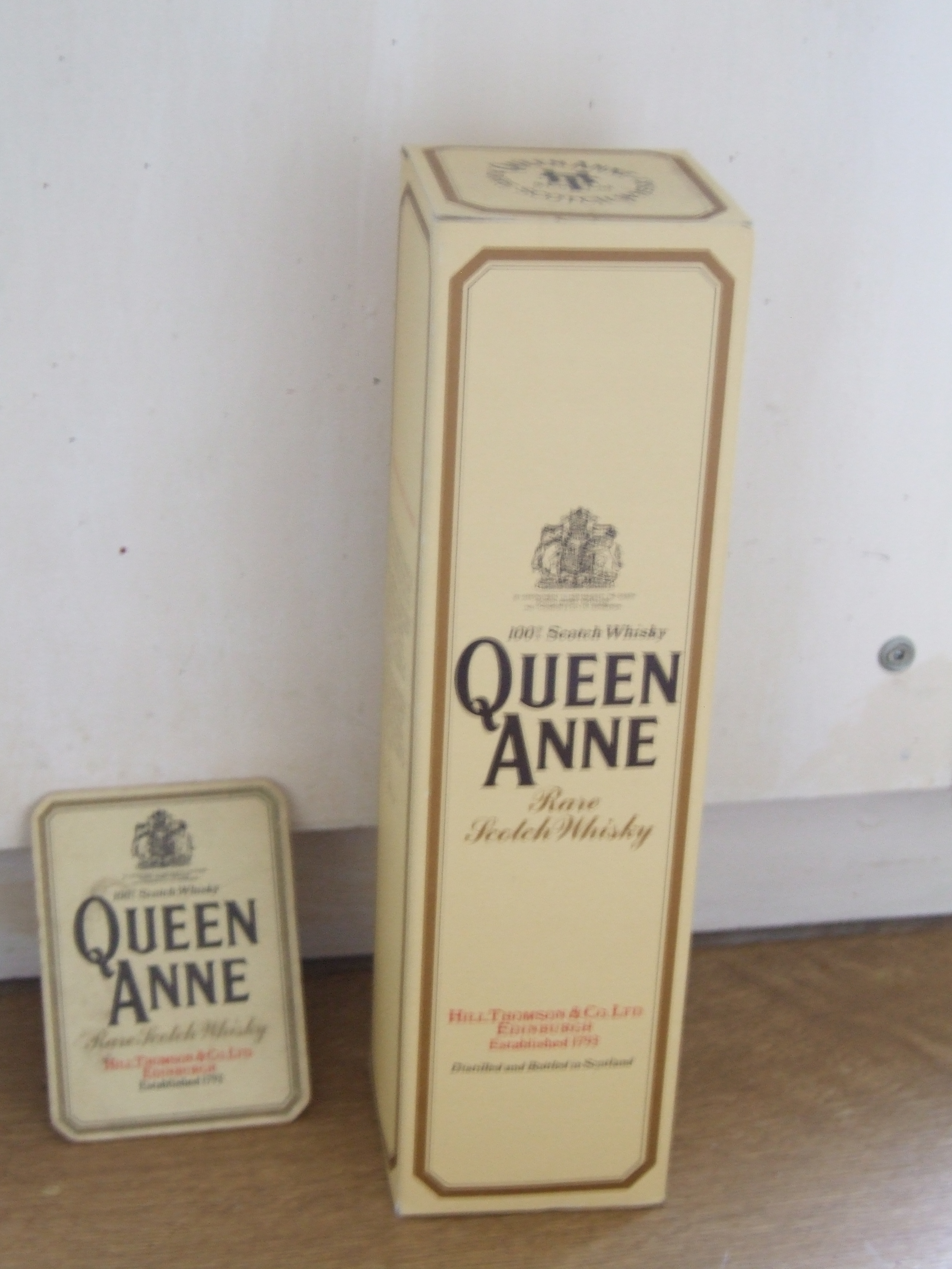
The “ignition key” for Queen Anne is kept in a key safe in the office at Aviemore along with other diesel loco keys etc.  On a whim, the term “queen anne keyring” was searched online and a Queen Anne whisky keyring came up on Ebay.  The price was £1.63 with carriage £1.90 + import VAT as it was located in the Netherlands.  So the key is now instantly recognisable inside the key safe.

Key Ring

Other Memorabilia

Gearbox

It was noticed around the time of the 2022 Diesel Gala that when using 1st gear to pull away with a load, the corresponding clutch would slip unless the clutch spring was tightened very much more than it should be.  2nd and 3rd gear worked without problems and provided the load is not too heavy, the loco will happily pull away in 2nd gear.

The Ruston design of gearbox fitted to Queen Anne and many narrow-gauge shunters was very successful and is a constant-mesh type that uses separate clutches to engage each gear.  The problem with 1st gear is most likely due to the corresponding friction pads being worn down to the rivets.

Dismantling the gearbox is quite straightforward, and fortunately we have the 48DS manual that gives full details of dismantling and servicing.  After removing the cab floor the upper gearbox casing is removed and lifted away.  It weighs 3 cwt (150 kg) so will probably require some sort of hoist.  After that the main gear assembly can simply be lifted out and taken to the bench for servicing.


The 1st and 2nd gear clutches are removed together.  The 3rd gear clutch which gives straight-through drive without reduction takes longer to remove.  The friction pad thickness can be observed without dismantling and the 3rd gear pads may not be renewed if they have sufficient thickness left.  There are a number of companies that replace clutch and brake friction pads on historic vehicles and it is hoped they will be able to refurbish the friction plates at reasonable cost.

The plan is to do this job over the winter.

Friday 25 March 2022

Latest Diesel Gala Video Uploaded

Here is a compilation of film clips of Queen Anne taken at the Gala on Friday 18th March :-


.

Monday 21 March 2022

Strathspey Railway Diesel Gala March 2022

Brakevan Rides

The Diesel Gala ran on Friday, Saturday and Sunday 18th to 20th of March.  Seven Strathspey-based diesels were in action. Class 27 (D5394), Class 31 (D5862) and Class 37 37674 were in action on the main line and shunters Class 08 (D3605), North British D2774, Ruston 48DS “Queen Anne” and Thomas Hill Vanguard gave top-and-tailed brake van rides at Boat of Garten and Aviemore.  An SRPS railtour headed by two Class 37s made and appearance on the Saturday.

At Aviemore, Queen Anne was at the south end of the brakevan and the Vanguard at the north.  The rides were in Aviemore yard, from the coal dock up to the headshunt.  There was no timetable - trips were made on demand.  Quite a number of people were carried and three dogs.

Queen Anne at the Coal Dock

... and the Vanguard

Both locomotives ran without problems.  It was a good workout for Queen Anne pushing hard from the back on the uphill northbound runs and doing most of the work on southbound runs.  The Vanguard was used to get the train rolling in both directions to avoid overloading the Slow gear clutch and to provide most of the braking effort.  Middle and Fast gears were mainly used and Queen Anne in Fast gear could just keep up with the Vanguard as it accelerated towards the end of the headshunt.  Over the three days about 9 gallons of diesel was used.

Loading up

Ready for off

On the move

Gone to lunch.  Back soon.

After her shakedown (literally) run, the next step will be to give Queen Anne a thorough examination to check for anything that may have worked loose or needs adjustment.  It was noted that the fan bearing was rather noisy and it will be replaced in due course.  It was not possible to fit the chain oiler system in time but this will be completed in the next few weeks.

Class 31 passing

Class 37 in background